
With a loss tangent of 025. 005 604 10 2 208 46 10 377 2 2 208 0.

The Geometry Of The Lossy Lhm Slab Between Two Lossy Dielectric Media Download Scientific Diagram
The numerical results demonstrate the feasibility of these internal antenna designs achieving broad bandwidth that is required for wireless communication systems.
. A lossy dielectric medium is defined as a medium in which the electric conductivity is not equal to zero yet it is not a good conductor. The dielectric properties are reported as the average of multiple measurements on different samples for each material. LOSSY MATERIALS LOSSY MATERIALS V20 Dielectric measurement of lossy solids and lossy liquids is conducted over 4 MHz 67 GHz using calibrated DAK-TL2 and DAK measurement systems respectively.
The insulator between the two metal plates of a capacitor would be a dielectric. A dB 8. A dielectric with some conductivity is considered lossy since a conduction current density will play a role that competes with the displacement current density.
The dielectric loss tangent tan δ of a material denotes quantitatively dissipation of the electrical energy due to different physical processes such as electrical conduction dielectric relaxation dielectric resonance and loss from non-linear processes 4. Lossy material Abstract. ε r 208 tan δ 00004 at 25 oC assuming frequency independence.
Rcrumpfutepedu Lecture Outline Lossy Dielectrics Power Slide 2. Time Constant provides an estimation of the relevant time scales for transient effects. This tool provides a quick calculation of lossy electrical properties from the input parameters to the left.
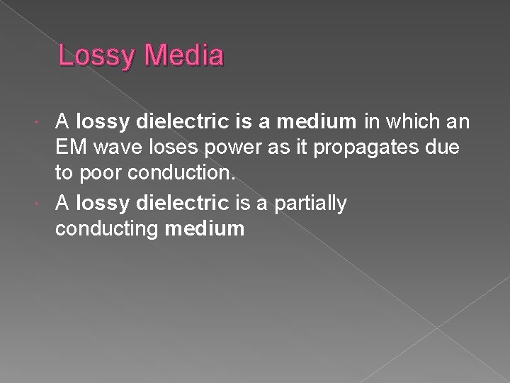
A lossy dielectric can be described as a medium where some fraction of the electromagnetic wave power is lost as the wave propagates. The general wave equations and the associated parameters expressed in Equations 112 to 122 therefore apply to lossy dielectric media. 0004 46 10 36 10 tan 2 10.
Electrical conductivity can be calculated from σ2πftanδεε 0 where f is the frequency in Hz ε is the real part of complex permittivity tanδ is the loss tangent and ε 0 is the vacuum permittivity. 686 604 10 100 0. Lossy Medium - Dr.
Conduction in a medium leads to Joule heat- ing which implies a loss of power which means that the electric and magnetic field amplitudes have to suffer from attenuation. These notes may contain copyrighted material obtained under fair use rules. Dielectrics that exhibit electromagnetic loss at microwave frequencies are used extensively in coupled-cavity traveling-wave tubes CCTWTs and less frequently in klystrons gyrotrons and gyro-klystrons as rf terminations to suppress unwanted oscillations and to reduce rf cavity Qs.
Ray Kwok Example a Calculate the dielectric loss in dB of an EM wave propagating through 100 m of teflon at 1 MHz. Written 44 years ago by govindkedar 220 modified 6 months ago by sagarkolekar 10k electromagnetic field and wave theory ADD COMMENT EDIT Please log in to add an answer. Lossy Dielectrics Before proceeding with a more detailed description it should be emphasized that the fact that in the time domain all the fields H x E y H z are real quantities.
A lossy dielectric medium is defined as a medium in which the electric conductivity is not equal to zero yet it is not a good conductor. At 130 Wm-K BeOSiC has a room temperature thermal conductivity that is more than a factor of two higher than the next best commercially-available lossy dielectric. For a lossy dielectric material having μ r 1 ϵ r 48 and σ 20 s m.
The loss angle δ is equal to 90 θ. Characterization of the lossy dielectric materials using contour mapping Review of Scientific Instruments. It must not pass current but must pass the field between the plates.
Dielectric Materials for Wireless Communication 2008 View all Topics. Thus accounting for loss is possible only through a non-zero conductivity σ of the medium. As for the lossy materials the measured relative dielectric constant and the loss tangent of alcohol are 6786 and 0895 respectively.
Setting σ 0 in Equation 112 leads to a non-zero attenuation constant α 0. Vol 89 10. Attenuation constant 훼 is the measure of the spatial rate of decay of the electromagnetic wave in the medium measured in nepers per meter Npm or in decibels per meter dBm.
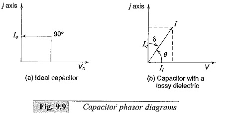
Loss in a less than perfect dielectric is usually expressed as heat. I 1 will be equal to GV where G represents the conductance of the dielectric material. Dielectric Loss refers to the Loss of energy that goes into heating a Dielectric material in a varying electric field.
This power loss is due to poor conduction. The materials frequency dependency is visualized according to the selected Start End and Resolution frequencies. Besides the measured dielectric constant of.
It tends to depend mainly on the Dielectric material and the frequency. When you click the button the data for the material below will update based on your input. The total current I I c I 1 jωC GV.
Calculate the propagation constant at a frequency of 16 GHz. Distribution of these materials is strictly prohibited Course Instructor Dr. Electromagnetic basis of microwave heating.
Where Here we have assumed that and. A lossless dielectric would be a dielectric material which does not dissipate EM energy due to poor conduction of the wave. B at 10 GHz.
The current leads the voltage by an angle θ which is less than 90. In this paper two possible internal antenna configurations that include lossy plastic chassis materials are studied using the IE3D simulation package. Dielectric Loss is measured using the Loss of tangent which is.

4 4 Wave Propagation In Lossy Dielectrics For I E S G A T E Youtube

Dielectric Medium An Overview Sciencedirect Topics

Lossy And Lossless Dielectric Loading H 8 Mm R 4 Mm Download Table

4 4 Wave Propagation In Lossy Dielectrics For I E S G A T E Youtube
2

4 7 Wave Propagation In Lossless Dielectric Free Space Youtube
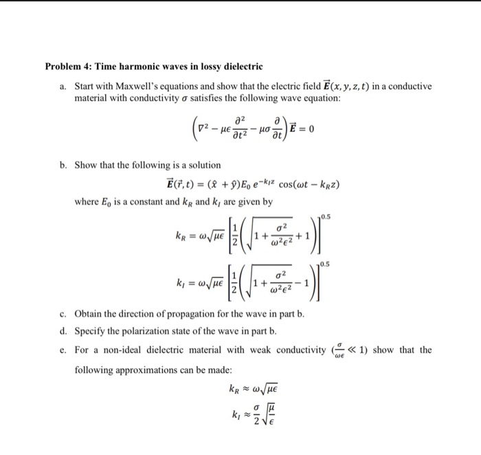
Solved Problem 4 Time Harmonic Waves In Lossy Dielectric Chegg Com

Dielectric Medium An Overview Sciencedirect Topics

Dielectric Medium An Overview Sciencedirect Topics
Chapter 2 Maxwell S Equations And Plane Em Waves
Dielectric Constant And Loss Capacitor Phasor Diagram Measurement Ranges

Parallel Equivalent Circuit Representing A Lossy Dielectric And The Download Scientific Diagram

Dielectric Properties Of Ceramics Ppt Video Online Download

Dielectric Properties Why They Re Important And How To Measure Them
Plane Wave Propagation In Lossy Media Asst Prof
Electromagnetic Field And Waves Gidong Lee Outline Electrostatic

Maxwell Wagner Equivalent Circuit Model Of A Heterogeneous Lossy Download Scientific Diagram

Parallel Equivalent Circuit Representing A Lossy Dielectric And The Download Scientific Diagram

Characterization Of The Lossy Dielectric Materials Using Contour Mapping Review Of Scientific Instruments Vol 89 No 10